
Data from all the Suunto dive computers can be downloaded to a personal computer, where you can cyber-dive and relive your greatest underwater moments to your heart's content. Besides reliving dives, the computer provides practical information such as calculated surface air consumption for each dive that can help you become a better diver.
Suunto makes the Dive Manager software (for Microsoft Windows only) available free on its web site. However, the interface cable that connects the dive computer to your personal computer lists for around $170. Many divers feel this is outrageous, as the interface consists of just a simple cable and a few common electronic parts.
A number of electronically oriented divers have thus embarked on projects to build their own homebrew interfaces. There are any number of these plans out there on the Internet. Early on, for example, I ran across one plan at the web site of the scuba club of the European Center for Nuclear Research, or CERN, in Geneva. This circuit looked fairly simple, based on a single IC chip and a few support components. What put me off it, however, is the fact that you have to "fine-tune" the circuit by adjusting a potentiometer to get the dive computer to talk to your PC fluently. Given that at that point in the project I would probably be dealing with other unknowns (Did I wire it correctly? Are the pinouts to the computer serial port right? Do I even remember which COM port this is for? etc), this sounded like more fussing than I'd want to deal with.
I then ran across a web site by Swiss diver Roli Wasmer at which he describes another homebrew approach to the Suunto interface. At first blush, this has approximately the same level of complexity as the other plan. Instead of an IC chip, however, it uses a few transistors. What was most important to me, though, was that the circuit required no fine-tuning with a trimmer potentiometer to get the interface to work. I decided to build it.
Before going farther, let me emphatically say that I don't want anyone blaming me if they try to build this and somehow fry their expensive Suunto dive computer! Although I found my Cobra to be tolerant of modest errors such as reversed leads on the contacts, Roli points out at his web site that with certain wiring mistakes it's possible to develop enough voltage across these contacts that you can indeed turn your Suunto to toast. Unless you own a soldering iron and voltmeter and have built electronics projects successfully in the not too distant past, I'd strongly discourage you from trying this project. If you do decide to try it, proceed at your own risk!
One of the first decisions I needed to make was what general construction method I was going to use. Many of my past electronics projects have been based on components mounted on perfboard (phenolic board filled with rows and rows of holes) with their wires twisted together underneath. This usually looks messy, though, and can be difficult to debug if there are problems. Since Roli included a plan for a printed circuit board, I thought I might try to see if I could cobble one together.
There are several technologies for making a printed circuit board from such a plan. Many sophisticated hobbyists use a photo technique that involves exposing an emulsion similar to photographic negative film. If I went out and invested in what I'd need, though, it would drive the project cost up unacceptably. Others use rub-on dry transfers to lay out the pattern on the board. Since this project involves a very simple circuit, though, I thought I could get away with a cheap and cheerful approach of "painting" the circuit freehand onto the board using nail polish.
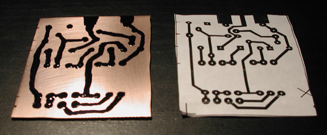 The picture at left shows the circuit after I've drawn it onto the circuit board
with dark nail polish. The board that I started with was faced with copper on one side,
but was not pre-drilled with any holes. I took Roli's plan and enlarged it somewhat before
printing it out; space was not at a premium for me, and I wanted some maneuvering room
for freehanding the painting of the pattern. After the nail polish was dry, I
submerged the board in copper sulfate solution, a
bottle of which I'd bought at the electronics store for about $4. This eats away all
of the exposed copper, but leaves intact the copper traces covered by the nail polish.
The picture at left shows the circuit after I've drawn it onto the circuit board
with dark nail polish. The board that I started with was faced with copper on one side,
but was not pre-drilled with any holes. I took Roli's plan and enlarged it somewhat before
printing it out; space was not at a premium for me, and I wanted some maneuvering room
for freehanding the painting of the pattern. After the nail polish was dry, I
submerged the board in copper sulfate solution, a
bottle of which I'd bought at the electronics store for about $4. This eats away all
of the exposed copper, but leaves intact the copper traces covered by the nail polish.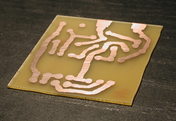 After rinsing and drying the board, I then soaked it in acetone to remove the nail polish.
After another rinse and some light rubbing with a Scotchbrite pad, the traces were complete.
After rinsing and drying the board, I then soaked it in acetone to remove the nail polish.
After another rinse and some light rubbing with a Scotchbrite pad, the traces were complete.
The final step to prepare the circuit board was to drill the holes that the wire leads of components would stick through. Fortunately I have a drill press, which made this a quick and easy job.
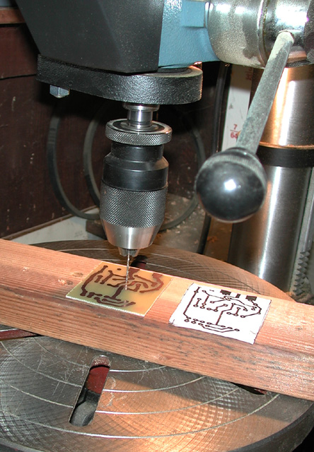 In the past I've noticed that Radio Shack sells inexpensive hand
drills, so I guess you could do this with one of them, or with a small bit in a
cordless or corded handheld electric drill. You need a steady hand, however, to make
sure that the drill doesn't wander.
In the past I've noticed that Radio Shack sells inexpensive hand
drills, so I guess you could do this with one of them, or with a small bit in a
cordless or corded handheld electric drill. You need a steady hand, however, to make
sure that the drill doesn't wander.With that it was then a simple matter to solder in the components. Semiconductors like transistors and diodes are sensitive to heat, so I had to make sure that I applied heat only briefly and/or used a heat sink of some kind to draw the heat away from the components as I worked.
I faced only two significant issues as I assembled the project. First, I had to make sure that I had the pinouts correct for the DB9 connector used to plug the cable into the serial port on my personal computer, so this involved a bit of hunting around on the Internet to verify this. Second, after I assembled and tested the project it didn't work the first time around. After debugging it I found that Roli's circuit board pattern seemed to assume a different arrangement of leads coming out of the transistors. Fortunately the lead arrangement was printed on the plastic bags that the transistors were sold in, so I checked these carefully and determined I needed to swap a couple of wires around on each one. (It's probably worth noting that I have a local diver friend who decided to build this interface, and he ran into exactly the same issue with the transistor leads and had to swap them around as I did. So it's worth running this question down if you build this.)
I didn't even try to build a slick mechanical interface to hold the contacts against the dive computer during downloading. Roli used spring-loaded contacts which I wasn't able to find in my local electronics store. Since I don't dive all that frequently, I opted just to connect the wires to a pair of handheld probes which I press against the dive computer when I download. One of these days I suppose I might try to hunt down the spring-loaded contacts and build a proper mechanism.
After building the project, I checked it over carefully to make sure that the wiring was correct. I then plugged it into the personal computer's serial port and measured the voltage across the two contacts that would be connected to the dive computer. This voltage fluttered around 3 volts or less. Finally I connected it to the dive computer and, with a certain amount of fussing with the dive manager software, got it to download.
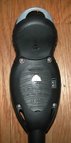 One final issue that I had to deal with was determining which contact was which on
the back of the dive computer. With trial and error I determined that the top
contact on the right of the Cobra as shown at left takes the signal lead, and the
lower contact takes the ground. The contacts on the Mosquito and D3 are similar;
I have no idea what the physical arrangement is for
the contacts on other Suunto models.
One final issue that I had to deal with was determining which contact was which on
the back of the dive computer. With trial and error I determined that the top
contact on the right of the Cobra as shown at left takes the signal lead, and the
lower contact takes the ground. The contacts on the Mosquito and D3 are similar;
I have no idea what the physical arrangement is for
the contacts on other Suunto models.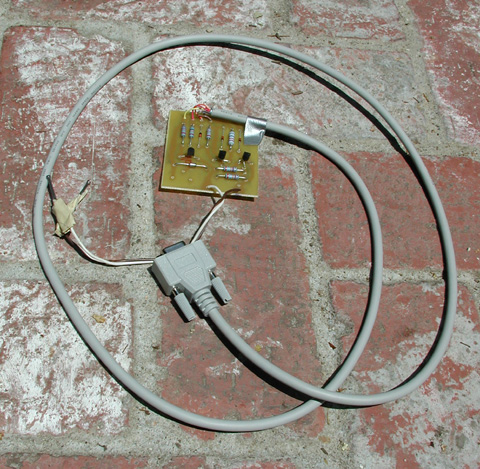 Here's the completed interface as I built it. After these photos were taken, I
eventually mounted it in a plastic box. It ain't necessarily pretty, but the main
thing for me is that it works, and it saved me something like $150.
Here's the completed interface as I built it. After these photos were taken, I
eventually mounted it in a plastic box. It ain't necessarily pretty, but the main
thing for me is that it works, and it saved me something like $150.
Note: After this was written, kits and low-cost interfaces were introduced by various third-party sources. In addition, Suunto appears to have new interfaces that plug into the PC's USB port that are cheaper than the earlier version of interface.